Arduino Pin Connections
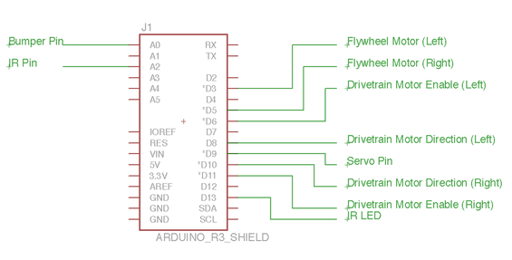
(i) = Arduino input (o) = Arduino output
Pin Connected To
A0 (i) Bumper
A2 (i) IR Circuit
D3 (o) DS3658 Driver – Pin 2 (Channel A)
D5 (o) DS3658 Driver – Pin 3 (Channel B)
D6 (o) L293 Driver – Pin 3 (Channel A Enable)
D8 (o) L293 Driver – Pin 2 (Channel A Direction)
D9 (o) Servo
D10 (o) L293 Driver – Pin 4 (Channel B Direction)
D11 (o) L293 Driver – Pin 5 (Channel B Enable)
IR Beacon Sensor
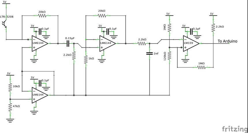
We designed one IR sensor to detect the 2-point basket, which outputs a 3kHz IR signal. This sensor has several stages, as shown below. Through these stages the circuit picks up IR light, filters out extraneous frequencies, amplifies the signal and converts it from analog to digital to be read by an Arduino.
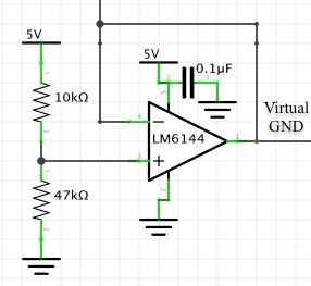
Virtual Ground
Legolas runs off a single supply voltage (2 batteries in series) so we offset the IR circuit voltage with a virtual ground. To allow for a range of IR signals we set the offset voltage close to the 5V positive supply voltage of the circuit.
Virtual Ground
Legolas runs off a single supply voltage (2 batteries in series) so we offset the IR circuit voltage with a virtual ground. To allow for a range of IR signals we set the offset voltage close to the 5V positive supply voltage of the circuit.
1. Transresistive Circuit
An LTR-3208 phototransistor outputs current proportional to the intensity of light incident on it. This current goes to the virtual ground through the transresistive circuit. The chosen LM6144 op amp allows the output voltage to go all the way down to ground before railing.
An LTR-3208 phototransistor outputs current proportional to the intensity of light incident on it. This current goes to the virtual ground through the transresistive circuit. The chosen LM6144 op amp allows the output voltage to go all the way down to ground before railing.
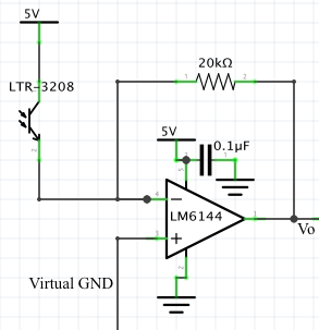
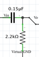
2. High Pass Filter
We used a high pass filter designed to attenuate the 120 Hz noise from indoor lighting. We also did this stage before amplifying the signal to prevent noise amplification. The corner frequency is:
We used a high pass filter designed to attenuate the 120 Hz noise from indoor lighting. We also did this stage before amplifying the signal to prevent noise amplification. The corner frequency is:
3. Amplifier
We used the LM6144 quad op amp chip from the transresistive circuit, in a non-inverting configuration, to amplify the filtered signal with a gain of 21.
This gain was chosen based on testing the circuit at similar distances to what are experienced during the bot's actual run. We were able to have a peak to peak output amplitude of 4.5V, giving us the ability to fine tune our detection thresholds.
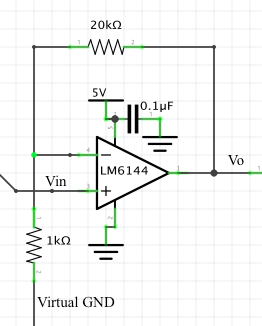
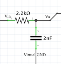
4. Low Pass Filter
A low pass filter was implemented to keep out any high frequency noise that may result from the other electronics on the bot, and specifically the four DC motors used for the drive train and fly wheel mechanism. We used a corner frequency one order of magnitude higher than the IR beacon frequency.
A low pass filter was implemented to keep out any high frequency noise that may result from the other electronics on the bot, and specifically the four DC motors used for the drive train and fly wheel mechanism. We used a corner frequency one order of magnitude higher than the IR beacon frequency.
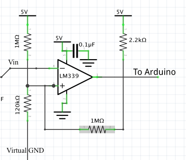
5. Schmitt Trigger
In the final stage of the circuit we used a Schmitt trigger to reduce the effect of noise and also to keep the comparator in the on state for a longer duration of time before turning off again. This also ensures the Arduino will be able to detect the circuit low output, because a longer fraction of the period is spent in the low state.
In the final stage of the circuit we used a Schmitt trigger to reduce the effect of noise and also to keep the comparator in the on state for a longer duration of time before turning off again. This also ensures the Arduino will be able to detect the circuit low output, because a longer fraction of the period is spent in the low state.
The Complete Circuit
Motor Drivers
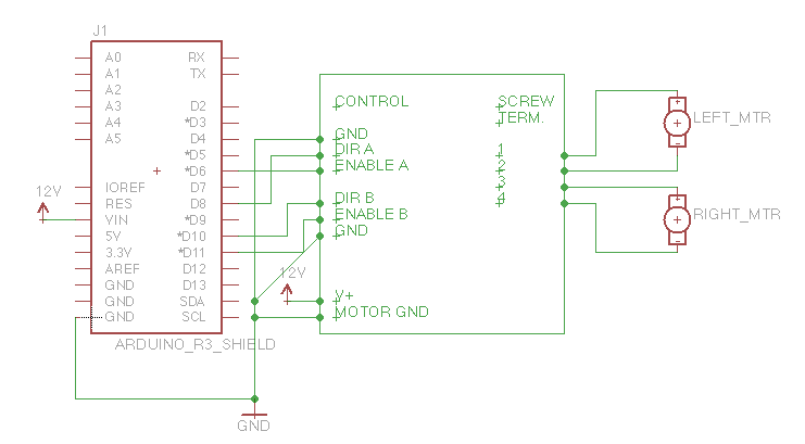
Drivetrain
Our drivetrain consisted of two Jameco DC motors (part No.164786) connected to the L293 Dual 1A H-bridge Module used in lab 3. These motors provided high torque, which helped our bot drive straight at low speeds. The H-bridge allowed us to drive either motor forwards or backwards for easy turning and reversing, and includes clamping diodes to protect the motors from inductive kickback.
Our drivetrain consisted of two Jameco DC motors (part No.164786) connected to the L293 Dual 1A H-bridge Module used in lab 3. These motors provided high torque, which helped our bot drive straight at low speeds. The H-bridge allowed us to drive either motor forwards or backwards for easy turning and reversing, and includes clamping diodes to protect the motors from inductive kickback.
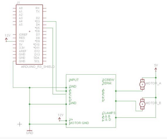
Flywheels
For our flywheel setup we drove two Jameco DC motors (part No.2173044) with the DS3658 Driver Module used in lab 3. This driver allows uni-directional speed control and provides kickback diodes. The schematic below shows how the motor driver was interfaced with the Arduino, and how the motors connected to the driver and power supply.
For our flywheel setup we drove two Jameco DC motors (part No.2173044) with the DS3658 Driver Module used in lab 3. This driver allows uni-directional speed control and provides kickback diodes. The schematic below shows how the motor driver was interfaced with the Arduino, and how the motors connected to the driver and power supply.
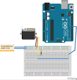
Ball Feeder
To feed nerf balls to the fly wheels we used a gate controlled by a servo motor. The servo input signal was tied to ground with a pull down resistor of 1K to prevent movement at startup.
To feed nerf balls to the fly wheels we used a gate controlled by a servo motor. The servo input signal was tied to ground with a pull down resistor of 1K to prevent movement at startup.
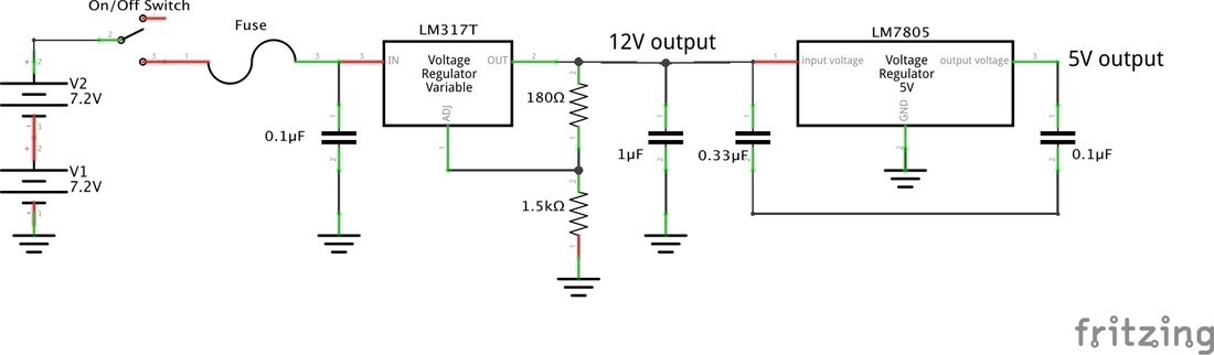
Power Circuit
Our power circuit provided two output voltages: one at 12V and one at 5V. We included a 1A fuse at the battery connection to protect the robot's electronics, and a switch to turn power on and off. An adjustable voltage regulator was used to provide 12V for the Arduino and drivetrain motor driver, and a fixed 5V voltage regulator was used to power the sensors, servo and flywheel motor driver.
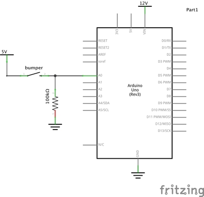
Bumper
We used a single bumper to detect walls. The bumper circuit consists of a switch and 100K pulldown resistor. The switch output is read by the Arduino to detect bumps.