State Machine Diagrams:
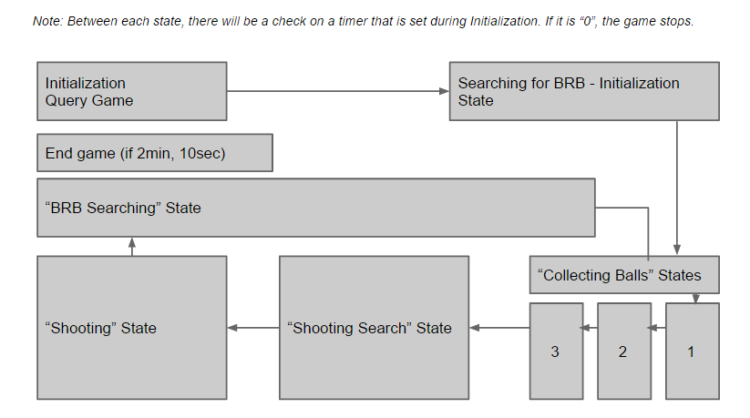
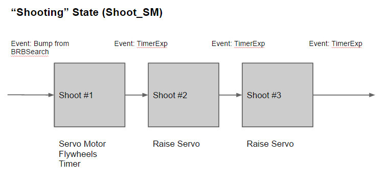
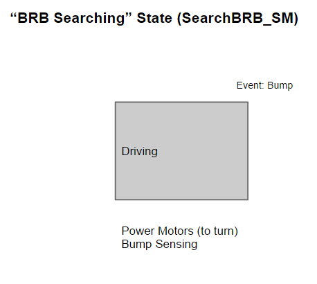
Our code looped through two primary functions: a case checker (LegolasCASE) and an event checker (LegolasEVENTchecker). Our state diagram, which is reflected in the case checking function, consists of two nested switch-case statements. The diagram below, shows the master state diagram - the higher level logic that dictates how the robot will perform at all times.
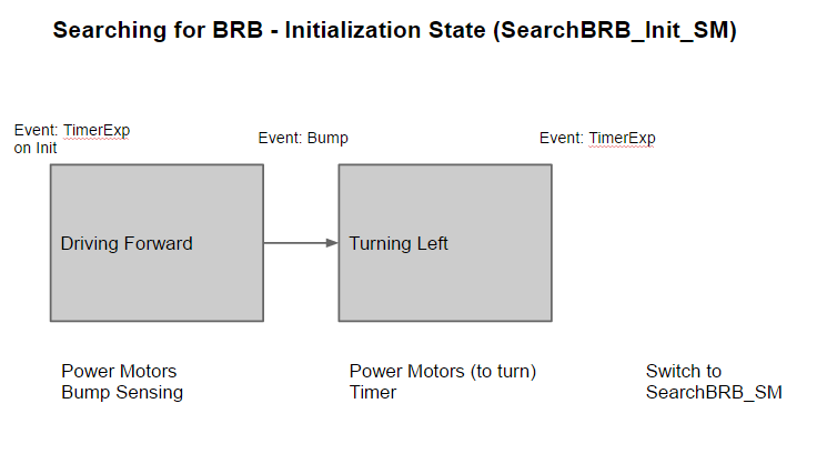
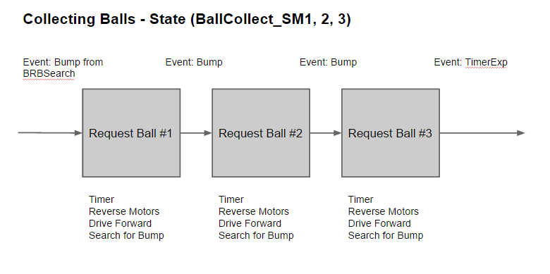
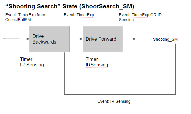
Within each state/case in the master diagram, there may be smaller activities: for example, in the "Shooting Search" state, the robot will drive in reverse, stop, drive forwards, and search for an IR trigger. These smaller/nested state diagrams can also be found in the gallery below.
Within each state/case in the master diagram, there may be smaller activities: for example, in the "Shooting Search" state, the robot will drive in reverse, stop, drive forwards, and search for an IR trigger. These smaller/nested state diagrams can also be found in the gallery below.