Full Design
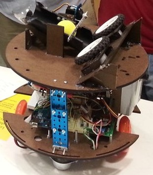
Our final bot, the proud archer Legolas. As you can see, we used a two leveled approach.
First Level
The first level held most of the bot's weight, including sensor, power, and drive train components. Find out more about the electronics in the Electrical Components section.
Second Level
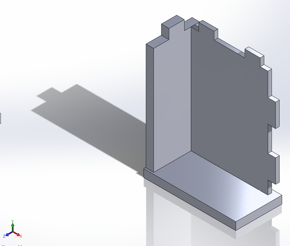
The top plate was the catcher, dispenser and shooter level. The power switch was also mounted on this level for easy access. The IR sensor carriage (white box on right side of the bot) was hung from the second level. You can see some rectangular slots under the flywheel board. This is where our carriage snapped into.
Supports
Initially we wanted to use threaded steel rods to connect the two layers together. The holes on the left side of the top plate were cut for this purpose. However this proved to be too shaky, especially since we were using a shooting system. If you look closely in the photo above, we used short rods to hold the silver casters in place however. We ended up attaching several RoboTerra pieces together to make column supports. They were hard to make the exact same height, but it worked out pretty well.
Motor Requirements
We noticed that as we added a second layer to our bot, the movement of the bot began to be severely effected and its turning was ineffective. We determined that our motors did not have enough torque to power our bot. We had done a lot of ground testing with one layer and only second layer testing with the bot resting on a tissue box (wheels off the ground) so we didn't catch this until late into our build. We also used the provided driver board (the one with both enable and direction outputs) to control their respective speeds. So we upgraded our drive motors to those that were slower but provided more torque. We were then to get pretty accurate control of each wheel.
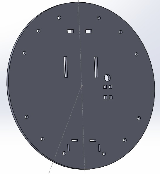
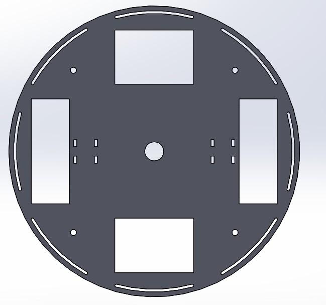
Electrical Components & Sensors Mounting
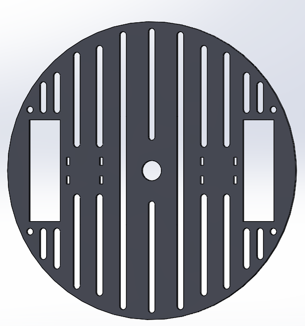
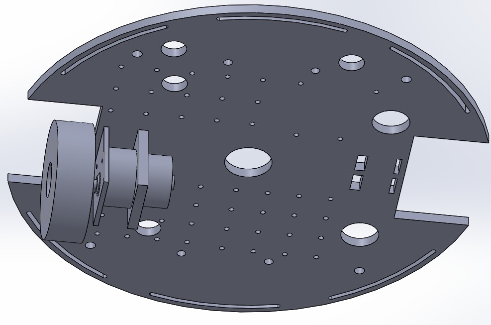
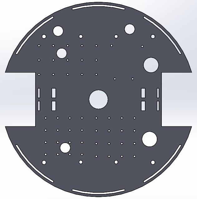
We used the following electrical components/sensors in our design: arduino uno, voltage regulators, L293 motor driver, DS3658 motor driver, bumper sensor, hi-tec servo, and photo transistor (with circuits to convert to an IR sensor). We placed all electrical components (including all breadboards) except for the servo and IR sensor, on the first level (model shown below). The bumper sensor was screwed down in one of the 6 bumper slots. The large holes were used for battery cables to run to the power supply circuit. In addition, some of these holes were used for the motor cables to attached to the driver/power circuits/arduino. All the very small holes were used to mount the driver and arduino in place (breadboards were glued down). There are a lot of them because that gave us the flexibility to move them.
The servo was mounted on furnished parts from RoboTerra (blue plates on picture above). The IR sensor breadboard was mounted (vertical-wise) to a carriage that hung from our second level.
Catching & Shooting System
We implemented a flywheel system to shoot on the two point basket. With the help of the IR sensor, Legolas would drive around and aim in the correct direction for the fixed flywheel position to shoot. Once Legolas stopped, the flywheels would activate and balls would be shot at one second intervals towards the hoop.
Catching/Storage
When the BRB sensor on the playing field was hit, one of the fellowship would drop balls into a tube for ball collection. The tube was 2+1/4" pvc pipe with the top half cut off. It was angled at approximately 30 degrees downwards. We placed a duron backing in the tube (so no balls would fall out during movement) and used the top of a plastic cup as a funnel in order to make placing the balls into the tubes easier. A servo gate held the balls in position.
Ball Dispensing
As mentioned above, we mounted a servo with a long metal rod as a gate for the balls. The balls would rest at the gate until the time to shoot. The servo would quickly open and close, allowing only one ball to go into the flywheel shooter at a time. The servo would pause for one second between balls to allow the flywheel to resume nominal speed.
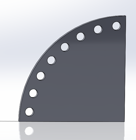
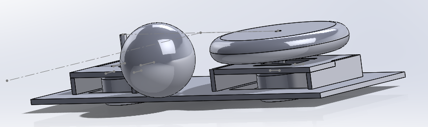
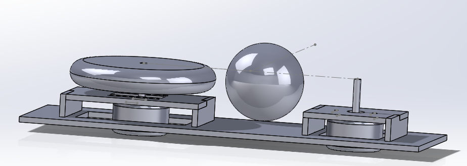
Flywheel Mechanism
To power our flywheels, we used two Jameco DC motors (found in the 210 supply closet) attached to large lego wheels. We found this to work well as the rubber wheels were able to spin fast with significant inertia. The two motors were mounted on a duron board using laser-cut mounts. The motors were screwed into the mounts, with one mount having a slider to move its motor an inch in either direction. This allowed us to easily tune the separation between the flywheels. The flywheel plate was then mounted at a 50 to 60 degree angle (based on trial and error). We used a provided motor driver and had the voltage supply to flywheels at around 5V.
The first level held most of the bot's weight, including sensor, power, and drive train components. Find out more about the electronics in the Electrical Components section.
Second Level
The top plate was the catcher, dispenser and shooter level. The power switch was also mounted on this level for easy access. The IR sensor carriage (white box on right side of the bot) was hung from the second level. You can see some rectangular slots under the flywheel board. This is where our carriage snapped into.
Supports
Initially we wanted to use threaded steel rods to connect the two layers together. The holes on the left side of the top plate were cut for this purpose. However this proved to be too shaky, especially since we were using a shooting system. If you look closely in the photo above, we used short rods to hold the silver casters in place however. We ended up attaching several RoboTerra pieces together to make column supports. They were hard to make the exact same height, but it worked out pretty well.
Motor Requirements
We noticed that as we added a second layer to our bot, the movement of the bot began to be severely effected and its turning was ineffective. We determined that our motors did not have enough torque to power our bot. We had done a lot of ground testing with one layer and only second layer testing with the bot resting on a tissue box (wheels off the ground) so we didn't catch this until late into our build. We also used the provided driver board (the one with both enable and direction outputs) to control their respective speeds. So we upgraded our drive motors to those that were slower but provided more torque. We were then to get pretty accurate control of each wheel.
Electrical Components & Sensors Mounting
We used the following electrical components/sensors in our design: arduino uno, voltage regulators, L293 motor driver, DS3658 motor driver, bumper sensor, hi-tec servo, and photo transistor (with circuits to convert to an IR sensor). We placed all electrical components (including all breadboards) except for the servo and IR sensor, on the first level (model shown below). The bumper sensor was screwed down in one of the 6 bumper slots. The large holes were used for battery cables to run to the power supply circuit. In addition, some of these holes were used for the motor cables to attached to the driver/power circuits/arduino. All the very small holes were used to mount the driver and arduino in place (breadboards were glued down). There are a lot of them because that gave us the flexibility to move them.
The servo was mounted on furnished parts from RoboTerra (blue plates on picture above). The IR sensor breadboard was mounted (vertical-wise) to a carriage that hung from our second level.
Catching & Shooting System
We implemented a flywheel system to shoot on the two point basket. With the help of the IR sensor, Legolas would drive around and aim in the correct direction for the fixed flywheel position to shoot. Once Legolas stopped, the flywheels would activate and balls would be shot at one second intervals towards the hoop.
Catching/Storage
When the BRB sensor on the playing field was hit, one of the fellowship would drop balls into a tube for ball collection. The tube was 2+1/4" pvc pipe with the top half cut off. It was angled at approximately 30 degrees downwards. We placed a duron backing in the tube (so no balls would fall out during movement) and used the top of a plastic cup as a funnel in order to make placing the balls into the tubes easier. A servo gate held the balls in position.
Ball Dispensing
As mentioned above, we mounted a servo with a long metal rod as a gate for the balls. The balls would rest at the gate until the time to shoot. The servo would quickly open and close, allowing only one ball to go into the flywheel shooter at a time. The servo would pause for one second between balls to allow the flywheel to resume nominal speed.
Flywheel Mechanism
To power our flywheels, we used two Jameco DC motors (found in the 210 supply closet) attached to large lego wheels. We found this to work well as the rubber wheels were able to spin fast with significant inertia. The two motors were mounted on a duron board using laser-cut mounts. The motors were screwed into the mounts, with one mount having a slider to move its motor an inch in either direction. This allowed us to easily tune the separation between the flywheels. The flywheel plate was then mounted at a 50 to 60 degree angle (based on trial and error). We used a provided motor driver and had the voltage supply to flywheels at around 5V.
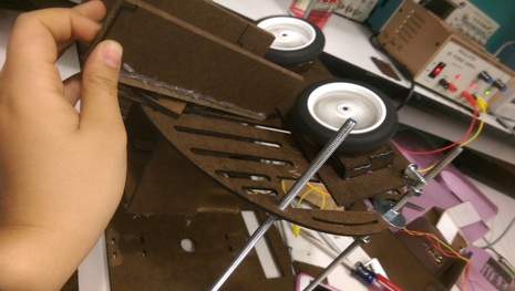
Early version of the flywheel
Design Sketches & Assembly